In this article we’ll look at how to adjust the azimuth of your turntable. This even works if your tonearm doesn’t actually allow this setting. All we need is a test record and construction paper. But before we roll up our sleeves, let’s take a look at what this setting does and what we can expect from it.
Why should you adjust the azimuth of your turntable?
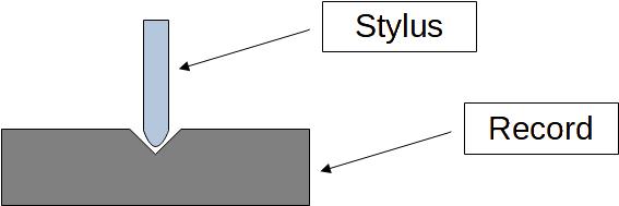
As we already know from this article, the signals of the right and left channels are perpendicular to each other. Both directions form a 45° angle to the surface of the record. With an ideal cartridge, as would exist in a perfect world, the stylus now slides perfectly vertically through the groove. A signal for, let’s say, the left channel leads to a deflection of the stylus at an exact 45° angle. This perfect deflection induces a voltage in the coil for the left channel in the cartridge, which is aligned at exactly 45° as well. In this example, the right channel is perfectly perpendicular to the left channel. Since the mechanical deflection is perfectly in perpendicular to the right channel’s coil, the stylus does not produce any signal in the right channel at all. We see a sketch of this fairy tale arrangement here:
But enough fairy tales, let’s get back to reality. You can certainly imagine that the stylus doesn’t slide perfectly vertically through the groove.
In addition, cartridges are precision parts that, despite the utmost care, do not have perfect alignment of the stylus and coils. If the groove only deflects a single channel, these two effects (non-ideal alignments of stylus and coils) mean that the other channel always receives a small portion of the signal. This process is called crosstalk or channel separation. The lower the crosstalk, the higher the channel separation. And the higher the channel separation, the better the spatial resolution and therefore the soundstage.
What you can expect from an azimuth adjustment
Let’s be honest: there will always be crosstalk. Conversely, channel separation will never reach 100%. But by carefully adjusting the azimuth of your turntable, you can minimize crosstalk to a reasonable minimum and thus get the best soundstage from your cartridge. Does that sound tempting? Then let’s move on to the practical part.
Before you adjust the azimuth of your turntable
Before we really get started, there are two more settings you should check. First, you should make sure that you have set your tracking force correctly. If you’re not sure how to do this, just read this guide. Second, check that you have the anti-skating adjusted appropriately. I have also put together a detailed guide on this topic.
Many roads lead to Rome…
There are several ways to adjust the azimuth of your turntable. We can divide them into visual and electrical approaches. Visual approaches boil down to optically aligning the cartridge so that it runs parallel to the record surface. To do this, you can either place a mirror on the turntable and align the cartridge parallel to its mirror image. Alternatively, some people stick a pencil lead on the cartridge and use a transparent set square to check that the lead runs parallel to the lines of the set square.
These visual approaches assume that the stylus is mounted exactly perpendicular to the cartridge and that the coils are installed 100% precisely within the cartridge. Unfortunately, these assumptions do not apply in practice, which is why visual approaches are only suitable for initial rough adjustments. In the end, it’s not about aligning the cartridge as parallel to the record as possible, but rather we want to achieve the highest possible channel separation.
…but only one leads to a decent soundstage
Since the visual approaches don’t really get us there, let’s focus on the electrical approach. To meaningfully minimize channel separation, we need to measure it. The test setup is that we use a suitable test record to alternately play back signals on the left and right channels. These signals pass through the stylus and the cartridge and after the preamplifier we can then measure these signals. The advantage of this approach is that we take both errors (alignment of the stylus and arrangement of the coils) into account in our optimization. If you’re a nerd, feel free to use your oscilloscope to measure. For everyone else, I recommend a computer with software for recording and editing audio signals, such as Audacity.
Measuring the crosstalk / channel separation
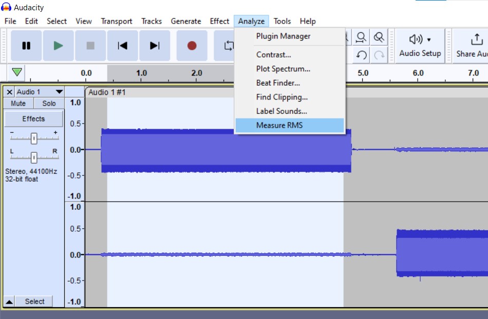
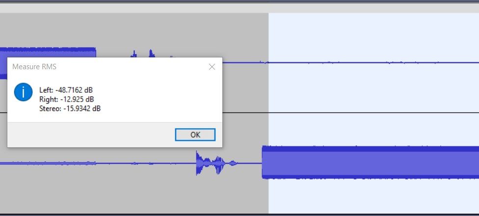
To set the azimuth correctly, we record the test track and look at the wave forms for both channels. What we are interested in are the amplitudes, i.e. the height of the curve shapes. For example, while the right channel is receiving its signal, at that time the amplitude of the left channel must be very low and vice versa. To keep things simple, we have a look at the signal levels expressed in dB. In Audacity, you simply mark the signal’s part you want to measure (bright background) and select Analyze –> Measure RMS.
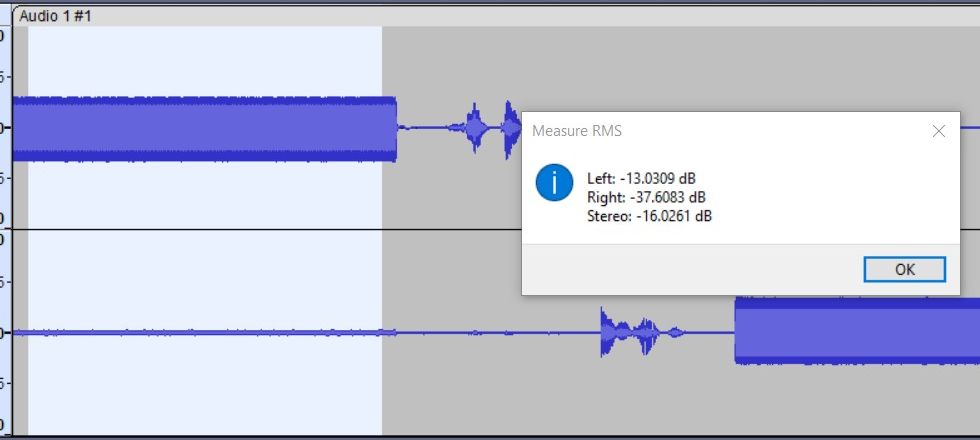
For our evaluation, we simply subtract the level of the inactive channel from the level of the active channel. You’ve probably already guessed: These difference values express your channel separations. The higher these difference values are and the closer the level values match, the better your soundstage gets. In the following example the active channels produce similar signal levels of -13 dB each. That doesn’t look too bad in the first run. The inactive channels however differ from -38 dB to -49 dB. In terms of channel separation, this means 25 dB vs. 36 dB. These results state a pretty unbalanced behavior, eventually leading to a mushy soundstage.
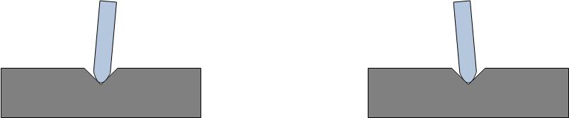
How to manipulate azimuth
In high-end tonearms there are special devices for adjusting the azimuth. If you don’t have such a tonearm, you still don’t have to shrug your shoulders. This is where the construction paper comes into play. To do this, we loosen the screws on the cartridge until we get a small gap between the headshell and the cartridge. With suitably cut shims made of construction paper, a (more or less) defined angle can now be set between the cartridge and the headshell. As with all settings, the following applies here: Don’t let yourself be unsettled. You won’t get the last fraction of a percentage. Fortunately, this is not necessary to achieve a significant improvement. Try it. It’s really worth it.